Interrupts and exceptions are special kinds of control transfer; they work somewhat like unprogrammed CALLs. They alter the normal program flow to handle external events or to report errors or exceptional conditions. The difference between interrupts and exceptions is that interrupts are used to handle asynchronous events external to the processor, but exceptions handle conditions detected by the processor itself in the course of executing instructions.
There are two sources for external interrupts and two sources for exceptions:
- Interrupts
- Maskable interrupts, which are signalled via the INTR pin.
- Nonmaskable interrupts, which are signalled via the NMI (Non-Maskable Interrupt) pin.
- Exceptions
- Processor detected. These are further classified as faults, traps, and aborts.
- Programmed. The instructions INTO, INT 3, INT n, and BOUND can trigger exceptions. These instructions are often called “software interrupts”, but the processor handles them as exceptions.
In order to ensure that these protected control transfers are actually protected, the processor’s interrupt/exception mechanism is designed so that the code currently running when the interrupt or exception occurs does not get to choose arbitrarily where the kernel is entered or how. Instead, the processor ensures that the kernel can be entered only under carefully controlled conditions. On the x86, two mechanisms work together to provide this protection:
1. The Interrupt Descriptor Table. The processor ensures that interrupts and exceptions can only cause the kernel to be entered at a few specific, well-defined entry-points determined by the kernel itself, and not by the code running when the interrupt or exception is taken.
The x86 allows up to 256 different interrupt or exception entry points into the kernel, each with a different interrupt vector. A vector is a number between 0 and 255. An interrupt’s vector is determined by the source of the interrupt: different devices, error conditions, and application requests to the kernel generate interrupts with different vectors. The CPU uses the vector as an index into the processor’s interrupt descriptor table (IDT), which the kernel sets up in kernel-private memory, much like the GDT. From the appropriate entry in this table the processor loads:
- the value to load into the instruction pointer (EIP) register, pointing to the kernel code designated to handle that type of exception.
- the value to load into the code segment (CS) register, which includes in bits 0-1 the privilege level at which the exception handler is to run.
The process of interrupt handling is shown as below: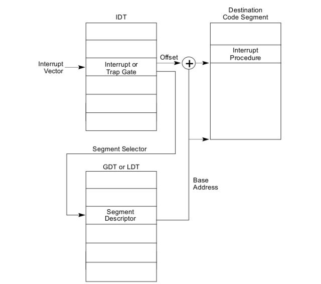
The IDT’s address is defined by a 48-bit register IDTR, which stores the IDT base address (bit 16 - bit 47) and IDT limit (bit 0 - bit 15). An IDT entry is specified by the interrupt vector. For NMI and exceptions, the interrupt vector is given by the processor automatically; for hardware interrupts it’s given by the I/O interrupt control chips; for software interrupts it’s from the operands of interrupt instructions. When an interrupt/exception happens, the CPU times the interrupt vector by 8 (each IDT entry takes 8 bytes) to access IDT, and fetch the corresponding descriptor.
The mechanism of the IDTR is shown as below: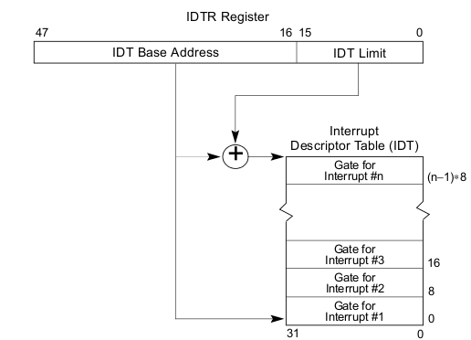
2. The Task State Segment. The processor needs a place to save the old processor state before the interrupt or exception occurred, such as the original values of EIP and CS before the processor invoked the exception handler, so that the exception handler can later restore that old state and resume the interrupted code from where it left off. But this save area for the old processor state must in turn be protected from unprivileged user-mode code; otherwise buggy or malicious user code could compromise the kernel.
For this reason, when an x86 processor takes an interrupt or trap that causes a privilege level change from user to kernel mode, it also switches to a stack in the kernel’s memory. A structure called the task state segment (TSS) specifies the segment selector and address where this stack lives. The processor pushes (on this new stack) SS, ESP, EFLAGS, CS, EIP, and an optional error code. Then it loads the CS and EIP from the interrupt descriptor, and sets the ESP and SS to refer to the new stack.
Details about how the TSS is used to protect the switching from user mode to kernel mode, and how are the stacks maintained during the process, can be found by reading the lab instruction page, Chapter 17 of book x86 Assembly Language - from Real Mode to Protected Mode, and Chapter 9 of the 80386 Programmer’s Manual.