Boot-up procedure: ROM BIOS -> Boot Loader -> Kernel.
BIOS sets up an interrupt descriptor table and initializes various devices such as the VGA display. After initializing the PCI bus and all the important devices, it searches for a bootable device and loads the 512 byte boot sector into memory at physical addresses 0x7c00 through 0x7dff, and then uses a jmp instruction to set the CS:IP to 0000:7c00, passing control to the boot loader.
The boot loader switches the processor from real mode to 32-bit protected mode. It also reads the kernel from the hard disk by directly accesing the disk device registers via the x86’s special I/O instructions. Then it transfers control to the kernel.
Exercise 2
A few step instructions were used to trace into the ROM BIOS and understand what it might be doing.
|
|
Below can be inferred from the above instructions:
- The IBM PC starts executing at physical address
0x000ffff0, which is at the very top of the 64KB area reserved for the ROM BIOS. - The PC starts executing with
CS = 0xf000andIP = 0xfff0. - The first instruction to be executed is a jmp instruction, which jumps to the segmented address
CS = 0xf000andIP = 0xe05b. - The instant number
0x0is compared with the value at memory address0xf6ac8. - The above mentoned value equals 0, since the address of the last instruction is
0xfe066, instead of0xfd2e1, which means thejne 0xfd2e1instruction didn’t take effect. dxis cleared to be 0 by the last instruction.
|
|
- Set stack segment from 0x0 to 0x7000 (stack top), as well as some other registers.
- The last instruction disables interrupts before entering the protected mode.
|
|
cldclears the direction flag, which is used to influence the direction in which some of the instructions work when used with the REP prefix.- Ports
0x70and0x71are used to control the CMOS device, referring to here. 0x8fis written to the port to close the NMI (non-maskable interrupt).
|
|
- Similar to above, port
0x92is set to 1 to indicate active lineA20, which is necessary to enter the protected mode.
|
|
- Load the GDTR (global descriptor table register), a 48-bit register that includes two parts, the base address and the boundary of the global descriptor table.
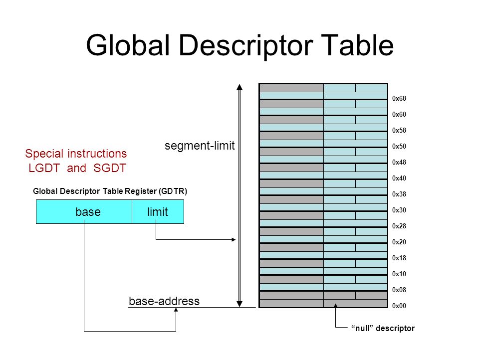
- The global descriptor table is used to save descriptors of each segment, such as CS.
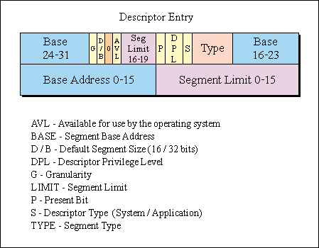
- Each descriptor takes 64 bits, detailed bits assignment see below:
- The
lgdtinstruction loads 6 bytes starting from%cs:0x6a74to GDTR.
|
|
CR0is a 32-bit control register, whose first bit (bit 0) is theProtection Enablebit.- The above three lines set the PE bit to be 1, to enable the protected mode.
|
|
0x8and0x10are segment selectors, which are basically the indices of entries in the GDT (seeP197of bookx86 Assembly Language - from Real Mode to Protected Mode).- More info can be found in the 11th chapter of book
x86 Assembly Language - from Real Mode to Protected Mode.
Exercise 3
Each ELF (Executable and Linkable Format) file is made up of one ELF header, followed by file data. The file data can include:
- Program header table, describing zero or more segments
- Section header table, describing zero or more sections
- Data referred to by entries in the program header table or section header table
Sections in the kernel ELF are:
LMA (load address) is the memory address at which that section should be loaded into memory.
VMA (link address) is the memory address from which the section expects to execute.
The boot loader (see boot/main.c) uses the ELF program headers to decide how to load the sections. The program headers specify which parts of the ELF object to load into memory and the destination address each should occupy. You can inspect the program headers by executing:
|
|
The areas of the ELF object that need to be loaded into memory are those that are marked as “LOAD”. Other information for each program header is given, such as the virtual address (“vaddr”), the physical address (“paddr”), and the size of the loaded area (“memsz” and “filesz”). In boot/main.c, the ph->p_pa field of each program header contains the segment’s destination physical address.
Exercise 5
Set the first breakpoint at 0x7c00, and change the link address from 0x7c00 to be 0x7e00 in boot/Makefrag. Beacuse the BIOS loaded boot loader into 0x7c00, the first couple of instructions don’t seem to have problem. However, the label addresses in the boot loader code have been changed, so the first instruction that will break is lgdt gdtdesc. By checking the contents of the label address, we’ll find that all 6 bytes of the GDTR will be filled with 0s, instead of the correct values.
|
|
The e_entry field in the ELF header holds the link address of the entry point in the program: the memory address in the program’s text section at which the program should begin executing.
The minimal ELF loader in boot/main.c reads each section of the kernel from disk into memory at the section’s load address and then jumps to the kernel’s entry point.
Exercise 6
The difference is because the kernel code was loaded to 0x100000 by the boot loader.
|
|