The first PCs, which were based on the 16-bit Intel 8088 processor, were only capable of addressing 1MB of physical memory. The physical address space of an early PC would therefore start at 0x00000000 but end at 0x000FFFFF instead of 0xFFFFFFFF. The 640KB area marked “Low/Base Memory” was the only random-access memory (RAM) that an early PC could use.
PC’s Physical Address Space
A PC’s physical address space is hard-wired to have the following general layout: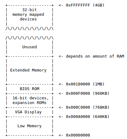
The 384KB area from 0x000A0000 through 0x000FFFFF was reserved by the hardware for special uses such as video display buffers and firmware held in non-volatile memory. The most important part of this reserved area is the Basic Input/Output System (BIOS), which occupies the 64KB region from 0x000F0000 through 0x000FFFFF. In early PCs the BIOS was held in true read-only memory (ROM), but current PCs store the BIOS in updateable flash memory. The BIOS is responsible for performing basic system initialization such as activating the video card and checking the amount of memory installed. After performing this initialization, the BIOS loads the operating system from some appropriate location such as floppy disk, hard disk, CD-ROM, or the network, and passes control of the machine to the operating system.
When Intel finally “broke the one megabyte barrier” with the 80286 and 80386 processors, which supported 16MB and 4GB physical address spaces respectively, the PC architects nevertheless preserved the original layout for the low 1MB of physical address space in order to ensure backward compatibility with existing software. Modern PCs therefore have a “hole” in physical memory from 0x000A0000 to 0x00100000, dividing RAM into “low” or “conventional memory” (the first 640KB) and “extended memory” (everything else). In addition, some space at the very top of the PC’s 32-bit physical address space, above all physical RAM, is now commonly reserved by the BIOS for use by 32-bit PCI devices. Recent x86 processors can support more than 4GB of physical RAM, so RAM can extend further above 0xFFFFFFFF. In this case the BIOS must arrange to leave a second hole in the system’s RAM at the top of the 32-bit addressable region, to leave room for these 32-bit devices to be mapped.
Memory Management
For 32-bit architecture PCs, there are two stages of memory management:
The calculation of the single-level/flat page table size:
Adding levels to the address translation process (hierarchical page tables) will reduce the size of the page tables. But it will add some overheads to the address translation process.
The image below summarizes both phases of the transformation from a logical address to a physical address when paging is enabled. The page translation mechanism uses 2-level page tables to converts the Dir, Table, and Offset fields of a linear address into the physical address: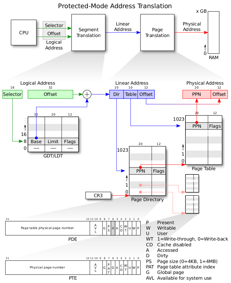
The addressing mechanism uses the Dir field as an index into a page directory, uses the Table field as an index into the page table determined by the page directory, and uses the Offset field to address a byte within the page determined by the page table. The physical page number (PPN) specifies the physical starting address of a page. Because pages are located on 4K boundaries, the low-order 12 bits (from bit 12 to bit 23) are always zero. In a page directory, the PPN is the address of a page table. In a second-level page table, the PPN is the address of the physical page frame that contains the desired memory operand.
Exercises
The solution code for the exercises of Lab 2 can be found here.
Exercise 1
When implementing the page_init function, it’s worth mentioning that the page tables were not allocated to physical memory address UTEMP (defined in inc/memlayout.h); instead, because in function mem_init the page directories and page tables were allocated using function boot_alloc, therefore, simply using boot_alloc(0) can point to the first free page after the memory chunk that stores page tables.
Exercise 2
For details about the segmentation mechanism, read the 10th and 11th chapters of book x86 Assembly Language - from Real Mode to Protected Mode. The paging machanism can be learnt from the lesson P3L2: Memory Management of the online Udacity course Introduction to Operating System, as well as the Intel 30386 Reference Manual.
Exercise 3
Inspect memory at corresponding physical (in QEMU monitor) and virtual addresses (in GDB):
Inspect detailed representation of the current page tables in QEMU monitor:
Show ranges of virtual memory that are mapped and their permissions in QEMU monitor:
Ctrl-a c is used to switch beween the QEMU serial console and monitor.Ctrl-a x is used to exit QEMU.
Exercise 4
It’s important to understand that the page_alloc in pgdir_walk allocates a page, in other words, it creates a page table, so page2pa(pp) in pgdir_walk returns the page table’s address. However, the function argument pp in page_insert represents a physical page frame, therefore the page2pa(pp) in function page_insert returns the page frame’s address.
Questions
Q: What entries (rows) in the page directory have been filled in at this point? What addresses do they map and where do they point?
A: See the table below:
Q: We have placed the kernel and user environment in the same address space. Why will user programs not be able to read or write the kernel’s memory? What specific mechanisms protect the kernel memory?
A: The permission bits/flags of PDE/PTE are used to protect the kernel memory.
Q: What is the maximum amount of physical memory that this operating system can support? Why?
A: The operating system uses a 4MB space at UPAGES to store the PageInfo structures. It can store 512 structures (a.k.a., 512 physical page frames) because each structure occupies 8B. The total amount of physical memory it can support is thus 512 x 4KB = 2GB. The maximum memory that can be used by the kernel is 256MB. Base address of mapped physical memory starts from virtual address 0xf0000000, which allows up to 256MB only.
Q: How much space overhead is there for managing memory, if we actually had the maximum amount of physical memory? How is this overhead broken down?
A: Up to 6MB + 4KB space overhead. page directory: 2^10 x 4B = 4KB; per PTE refers to 4KB physical memory, then per PT refers to 2^10 x 4KB = 4MB physical memory, needs 2GB/4MB = 512 page tables which takes 512 x 4KB = 2MB; PageInfo structures: 4MB.
Q: Revisit the page table setup in kern/entry.S and kern/entrypgdir.c. Immediately after we turn on paging, EIP is still a low number (a little over 1MB). At what point do we transition to running at an EIP above KERNBASE? What makes it possible for us to continue executing at a low EIP between when we enable paging and when we begin running at an EIP above KERNBASE? Why is this transition necessary?
A: After the instruction “jmp *%eax” we transition to running at virtual kernel address. The low 4MB of virtual address was mapped to the low 4MB physical address. The transition allows user programs to use the low address space.